Technology Tip: Proportional Integral Derivative (PID) Controllers
By Peter Ruplinger
Reprinted from Utah Molders Quarterly Newsletter December 2006
Our last three technology tips addressed sensors commonly found on injection molding machines. This issue will discuss proportional integral derivative (PID) controllers.
When setting up or adjusting any system be sure to read and follow the manufacturer’s instructions.
PID is a mathematical algorithm which very accurately controls temperature, pressure or flow. In modern injection molding machines this controlling algorithm is typically programmed into the central processing unit (CPU). Temperature and pressure sensors are connected to input boards on the CPU. Output boards send signals to valves, pumps, solid-state drives, and heavy-duty relays (contactors) which control heaters, motors or valves.
On older machines which rely on relay logic rather than a CPU, PID control is implemented with stand-alone controllers. They are modular and can be easily replaced. The older stand-alone controllers were about three inches
wide, seven inches high and eleven
inches deep. Newer stand-alone PID
controllers are typically only two by two
inches on the face and five inches deep. This size is referred to as “quarter DIN”. Stand-alone PID controllers are found on most mold temperature controllers and numerous other independent devices where precise control is necessary. A stand-alone temperature controller will always have a light emitting diode (LED) display of the set-point and actual state (process variable) of the system. They may also have LEDs to indicate alarm states. Many models have alarm contacts on the backside. Alarm contacts are usually rated for only one tenth or one quarter amp of resistive load. There will be some sort of password or jumper to prevent tampering.
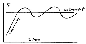 |
| Simple On-Off Temperature Control |
If we draw a diagram of the temperature
variance in your home, it would look
like a wave with peaks and valleys. |
In the early nineteen hundreds steam engines were widely used for pumping applications. This necessitated an engineer to constantly regulate the engine’s throttle. One creative engineer came up with the idea of hooking the supply line at the bottom of his water tower to a heavy rubber diaphragm. As water pressure increased the diaphragm would bulge out, pushing a rod which would turn off the throttle. When pressure subsided the rod moved in, and steam turned on again. It was a marvelous invention and was quickly accepted.
This was a simple on-off control. You all have such a control in your homes. It is the temperature control for your furnace. It doesn’t have a rubber diaphragm, but works on a similar principal. It turns on when the home is cold and off when hot.
A refinement of this basic idea incorporated a fulcrum and a lever so that movement of the diaphragm could result in a greater or lesser movement of the throttle. Furthermore, instead of just being on or off, the throttle could be on more if the water pressure was especially low, or on less if it was high. This was the first “proportional” control. Fisher Instruments claims fame to this invention. The result was a smoothing out of the valleys and peaks associated with simple on-off controls.
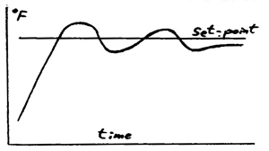 |
| Proportional Control |
Proportional Control dampens
oscilations over time. |
Proportional control by itself typically never reaches its exact target or “set-point”. The actual pressure achieved “process variable” was usually not reached by a specific amount known as the “integral”. When regulating water pressure in a culinary water system a small discrepancy is not important. When regulating pressures and temperatures in a process such as making vitamin C or nitro-glycerin, the pressures and temperatures are very critical.
Consequently during WWII more elaborate systems were developed to eliminate this “integral” discrepancy between the set-point and process variable. The systems were still mechanical, utilizing air or gas pressures which actuated rubber diaphragms or metallic bellows. These mechanisms often resembled coo coo clocks with all sorts of springs, gears and pulleys. Indeed many of the early instrumentation technicians had prior experience as jewelers. The result was a system which would eliminate the integral. After a few oscillations above and below the set-point, the process variable would stabilize at or close to the set-point.
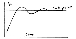 |
| Proportional Integral (PI) Control |
PI Control enables more
precise temperature control |
Proportional Integral (PI) control did not however eliminate the initial overshooting oscillation. The overshooting was eliminated with a much more sophisticated controller known as the “Proportional Integral Derivative” (PID) controller. This was an even bigger and more elaborate coo-coo clock. They were expensive, difficult to set-up and even harder to maintain. They still usually relied on air pressure from sensors and used air to activate valves. Fortunately with the advent of micro-circuitry, much cheaper and smaller PID controllers were soon developed. With PID controllers, the rate of change, “derivative” of the process variable is determined and output to the system is adjusted to eliminate overshooting.
Early electronic PID controllers were difficult to program. Process engineers often had to attend a two-day seminar to learn set-up procedures. In about 1980 PID controllers with “auto-tune” features were developed. This made set-up much easier.
Modern injection molding machines have auto-tune. They automatically calibrate the algorithm when the machine first warms-up. Typically the machine will overshoot a little, but after this first warm-up it has self taught how to avoid overshooting. The temperature is then regulated with-in one to three degrees F.
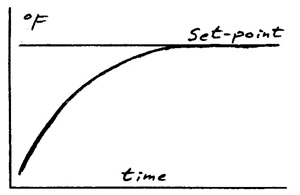 |
| Proportional Integral Derivative (PID) Control |
| Modern PID Controllers eliminate overshooting. |
Setting-up a stand-alone PID controller is a little more complicated. The technician has to set dip-switches on the back of the controller indicating what kind of signals the input and outputs use. For example is the input a type K or J thermocouple? Is it a resistive temperature detector (RTD)? Is it a 4 to 20 milli-amp signal? Or is it a zero to five volt signal? If the input is 4 to 20 milli-amps or zero to five volts, it will probably need to be scaled. This is a simple procedure where the technician tells the controller what the high and low values coming from his sensor are equal to. This process is not difficult, but takes an hour or so studying over the instructions the first time.
Likewise, the outputs on a stand-alone controller need to be set-up. Outputs to a variable pump are typically analog, 4 to 20 milli-amps. The heavy electrical loads for heaters are switched by large mechanical relays known as “contactors”, or much smaller solid state relays. The signals sent from the controller to relays is typically 24 volts D.C. and either on or off. On-off control is called “discrete”.
In discrete temperature control on-off time is proportioned, so the temperature stabilizes exactly where it should be.
PID algorithms are also available for DOS and Windows based systems. When using a personal computer to regulate processes, the inputs and outputs must be isolated from the computer, typically by Opto-22 input-output (I/O) boards. Isolated boards keep electrical spikes and noise from disrupting even ruining the computer.
The term “closed-loop” is nothing special. All it means is there is feed back to a controller. The thermostat on your home furnace is closed-loop. So don’t be impressed when you hear “Our system is closed-loop”. Furthermore, PID controllers are not hot stuff either. They’ve been around a long time. In the past they were somewhat costly and only used in critical applications. In recent years PID is standard equipment on most injection molders.
Our next Technology Tip will discuss fuse protection. There is a lot more to it than amperage.
Primer on Fuses
